Virtualizing pfSense with VMware vSphere / ESXi
This article is about building a pfSense® virtual machine on vSphere / ESXi. Article explains how to install any major pfSense software version on VMware vSphere versions 5.x and 6.x. The article does not cover how to install vSphere or how to configure pfSense software to do any of the many amazing things it can. A basic, working, pfSense virtual machine will exist by the end of this document.
Note
If the pfSense firewall will be running as a perimeter firewall for an organization and the “attack surface” should be minimized, many will say it is preferable to run it unvirtualized on stand-alone hardware. That is a decision for the user and/or organization to make, however. Now back to the topic.*
We’re going to start at the point where we have a vanilla ESXi install and have connected to it using the vSphere client. If other VMs are already running on ESXi, then it is not likely necessary to follow the networking steps too closely. However, we recommend skimming through it to see what is suggested before building the pfSense virtual machine part.
Assumptions
vSphere host is up and running
The reader has an understanding of network addressing
You have already uploaded pfSense installation .iso to the datastore.
Installing pfSense Software on vSphere 6.x using vSphere web client
The following steps include the necessary vSphere web client configuration required to get pfSense VM running. After getting to the pfSense setup step, switch to the guide for vSphere client below.
Basic vSphere web client networking setup
Before creating a new VM in vSphere web client, you will need to create two virtual switches and two port groups. We will first create Virtual switches for WAN and LAN and after that two port groups for the WAN and LAN.
From the vSphere web client navigator, click on Networking and then click on Virtual switches tab. From there, click on “Add a new standard virtual switch”.
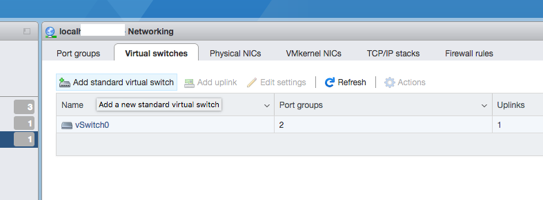
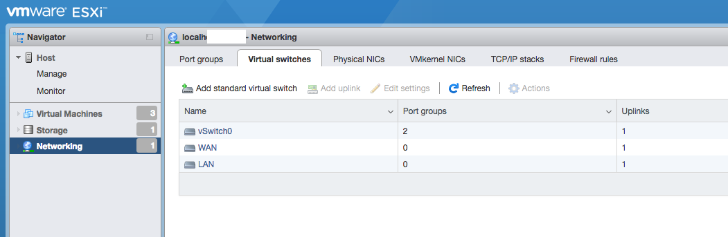
Add two Virtual switches, one for WAN and another for LAN. For uplink select two separate available ports.
Creating port groups
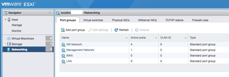
After creating Virtual switches, click on Port groups tab. On the Port groups tab click on “Add port group”. Add WAN and LAN port groups, each using WAN and LAN switches respectively.
Creating a pfSense VM
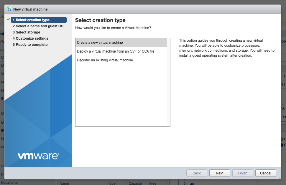
Now that the networking part is done, we continue to create a virtual machine. From the dashboard click on “Create/Register VM”. On the first wizard screen select “Create a new virtual machine”.
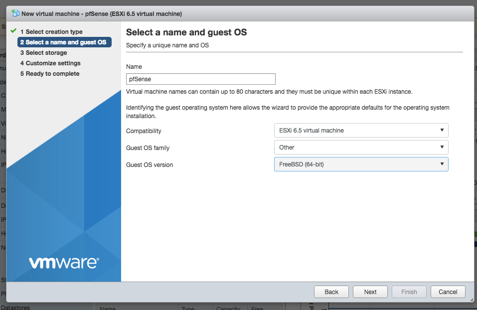
On the second page of the wizard, enter a name for your VM and select correct Guest OS version.
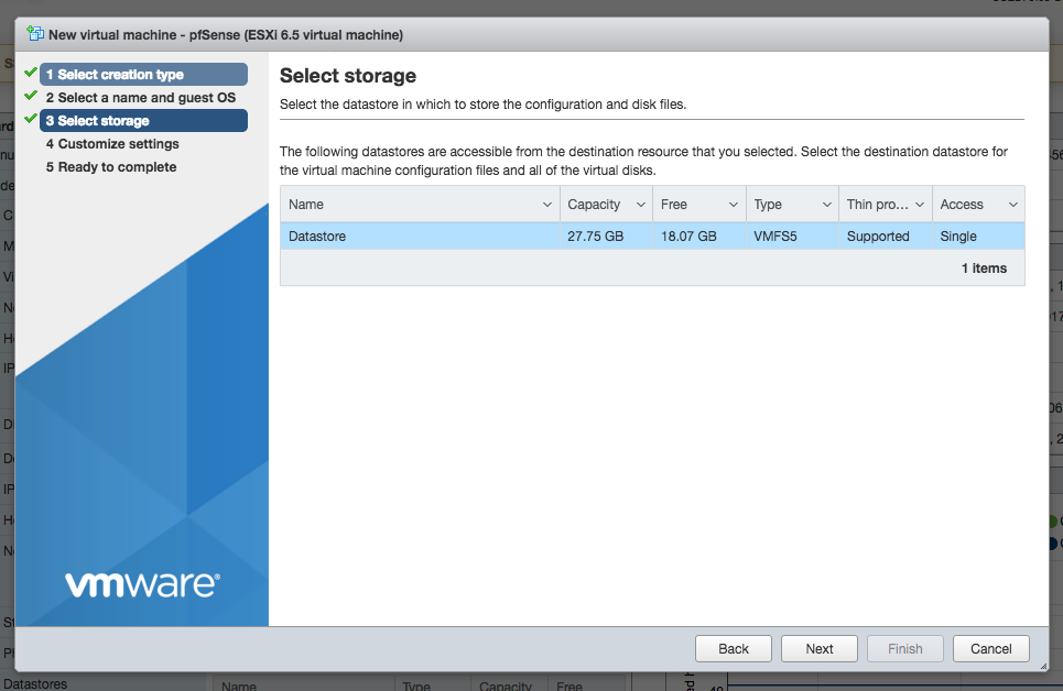
On the third page of the wizard, select the datastore where you want to keep your pfSense VM.
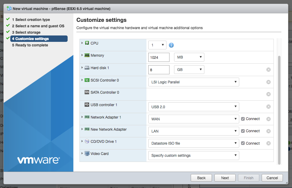
On wizard page four, add another Network Adapter and select the WAN and LAN port groups for each of the network adapters. Modify other virtual machine settings to your liking. For best performance, we recommend using VMXNET 3 type of adapters instead of E1000. However, with VMXNET 3 interfaces type you will have to manually assign interfaces with the first boot. For the purpose of this guide we used E1000 adapter type.
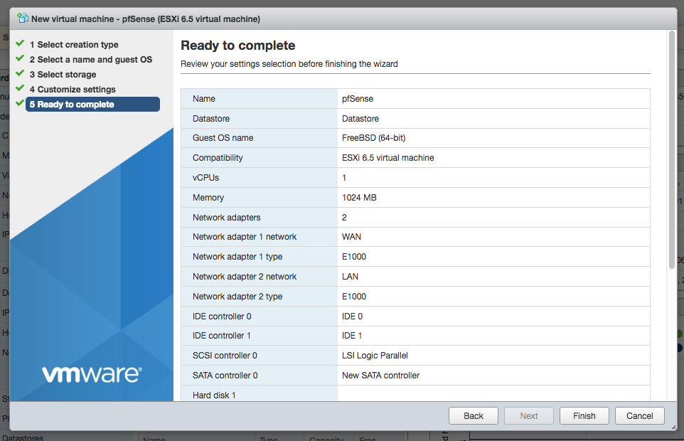
On the final wizard screen confirm the settings and click finish.
pfSense software installation
Once the pfSense virtual machine is created, under vSphere web client navigator click on “Virtual Machines” and select your newly created VM.
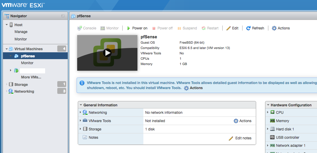
Power on the virtual machine.
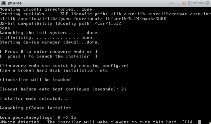
On the next screen, press “I” to invoke installer mode.
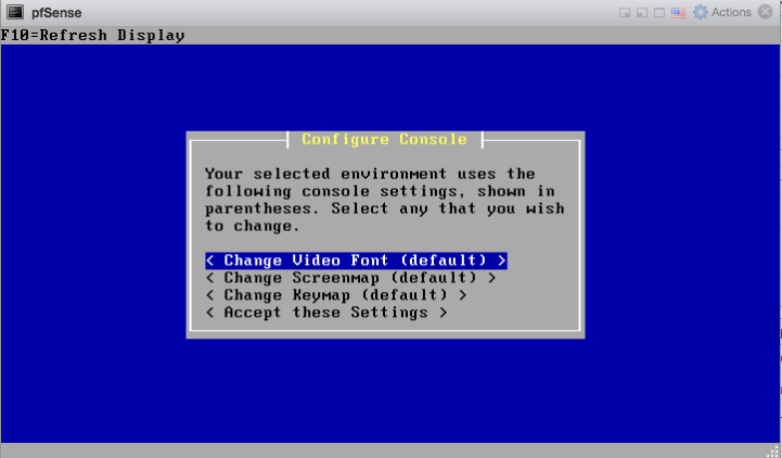
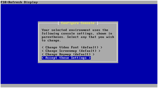
After the pfSense installer boots you will be greeted by the setup wizard. Select “Accept these settings”
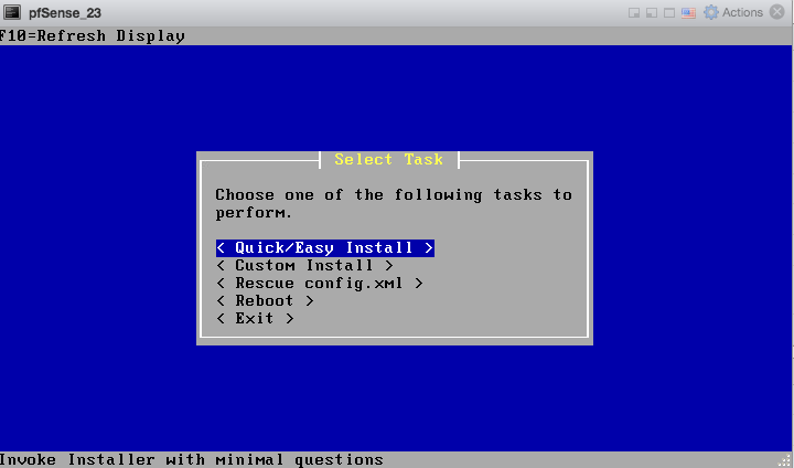
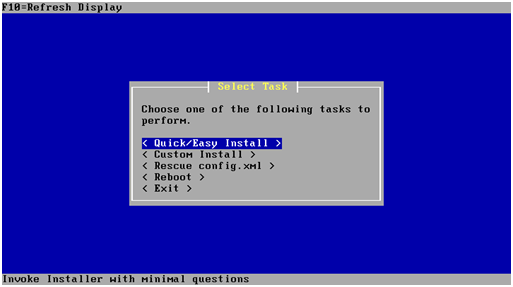
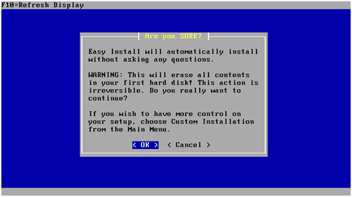
On the following screen choose “Quick/Easy Install” after which installation starts.
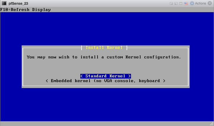
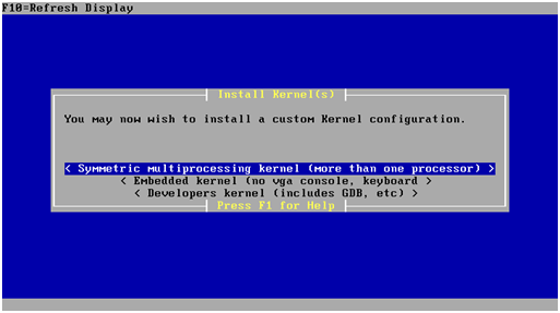
When prompted, select “Standard Kernel”.
After that installation completes and pfSense software boots up for the first time.
Installing Open-VM-Tools
Once the pfSense installation is complete, upon first boot install the Open-VM-Tools. Reboot is not necessary afterwards, however make sure the Open-VM-Tools service is running under Status > Services.
Congratulations, you have successfully completed pfSense installation on ESXi!
Installing pfSense Software on vSphere 5.x using vSphere client
Basic vSphere Networking
About vmnics, vSwitches, management and virtual machine networks
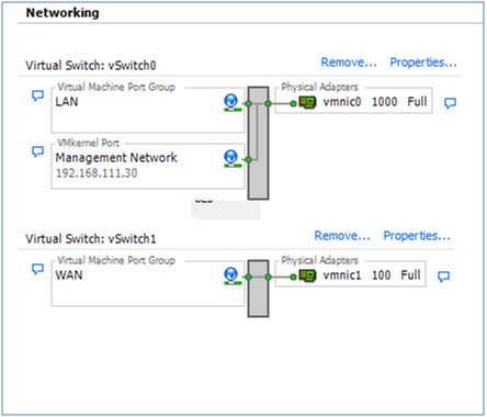
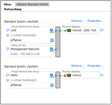
In the vSphere client the network diagram for an ESXi host may be viewed by clicking Networking on the Configuration tab:
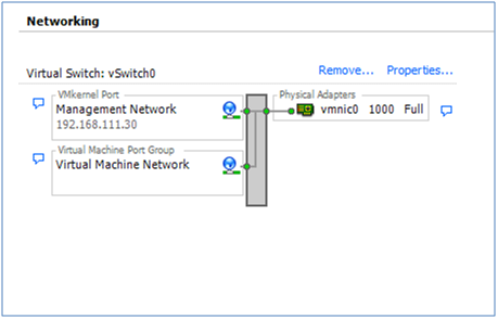
After ESXi was installed, before it was possible to connect to it with the vSphere client, a physical network adapter (a “vmnic” in the diagram) had to be nominated to be the ESXi Management Network. An IP address also had to be assigned to Management Network interface on the the ESXi host, either through DHCP or manually through the console.
The network diagram above shows that the Management Network was assigned to vmnic0 and it has an IP address of 192.168.111.30. (192.168.111.0/24 is my home LAN. Others will most likely be different.) Whatever subnet was chosen, the VMkernel Port in the diagram is the Management Network and that’s what the vSphere client is now talking to.
ESXi will name the first physical NIC it finds vmnic0. If vmnic0
is the management interface, ESXi will have automatically attached a
virtual switch, vSwitch0, to that interface.
In addition to the VMkernel port, ESXi will also attach a Virtual Machine Port Group to the vSwitch. In the diagram above it’s labeled as “Virtual Machine Network”. The VM Port group is where Virtual Machines can be attached to this virtual network.
In summary, in the above diagram, vSwitch0 has both a VM Port Group (Virtual Machine Network) and a VMkernel Port (Management Network) attached.
Creating the LAN
In a small network it is quite common to use the Virtual Machine Port Group on vSwitch0 to provide the LAN interface for the pfSense firewall. That allows access to the LAN side of the pfSense virtual machine and to manage the ESXi host with the vSphere client from a single PC. Of course, the virtual machine (e.g., the pfSense firewall) and the ESXi management interface must have different IP addresses.
COMMENT: I must say here that I always separate the ESXi Management network from other networks. I won’t go into the detail but there are some very good reasons for doing this. Without using VLANs, though, separation would mean that an additional NIC on the ESXi host would be dedicated only for ESXi management. What’s more, another NIC would be required in the vSphere client PC to connect to the management NIC on the ESXi host. To follow that path and enough NICs are available, simply delete the Virtual Machine Port Group by clicking the Properties link above **vmnic0*, highlight the VM Port Group and click Remove.*
Assuming there are only two NICs in the ESXi host, rename the VM Port Group from “Virtual Machine Network” to something a bit more meaningful. Click the Properties… link for vmnic0:
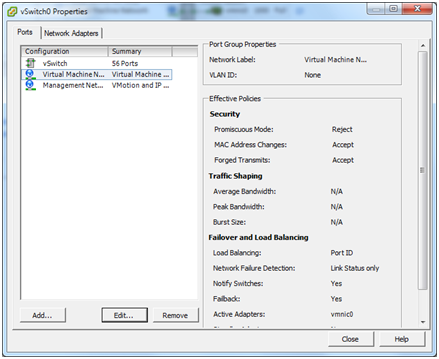
Highlight the Virtual Machine Network and click the Edit button.
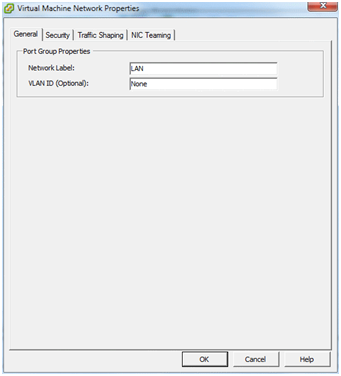
Change the Network label to “LAN” and click OK then Close.
This makes life a little easier when we assign virtual network interfaces to the pfSense instance.
Creating the WAN
As we’re not going to deal with VLANs here, a second physical NIC is required in the ESXi host. This will be the WAN interface.
HINT: If multiple physical interfaces are available in the ESXi host, it can be a bit of a struggle to work out which one has been identified as vmnic1, vmnic2 and so on. If the MAC address of each NIC is noted down along with the slot it occupied when it was installed in the machine, look at the Network Adapters screen under the Configuration tab to match up the MAC addresses (new to ESXi 5). However, having that foresight is rare, so lacking that information the easiest way to match physical NICs to vmnics is to plug a PC or switch into them, one at a time. The speed and duplex on the Networking or Network Adapters screens should change as the interface comes up. Because VMware didn’t provide a Refresh link on the Network Adapters screen, refresh by navigating to somewhere else then going back.
Now we need to link the second physical NIC (vmnic1), to a new vSwitch. Click the Add Networking link at the top right of the Networking screen and the following dialog will appear.
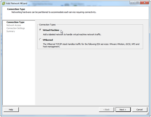
We are adding a Virtual Machine network so select that option and click Next.
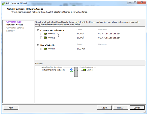
We want this NIC to be attached to a new vSwitch so select Create a virtual switch and check vmnic1. Click Next.

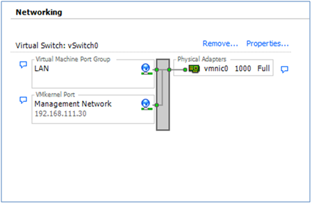
As we did with the LAN, let’s give this VM Port Group a more meaningful name of “WAN”. Click Next.
The next dialog simply confirms that everything looks OK. Click Finish.
The networking diagram should now look like this:
Now we can configure a new virtual machine on which pfSense software will be installed.
Configuring the Virtual Machine
Right click the ESXi host in the left pane of the vSphere client and select New virtual machine…
Configuration
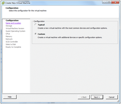
In the Configuration window, I always like to take the Custom option. (I’ve never really trusted what someone else thinks is “typical”). Click Next
Name and Location
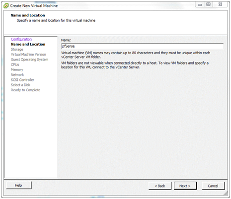
In the Name and Location window, let’s give the virtual machine a meaningful name like “pfSense” and click Next
Storage
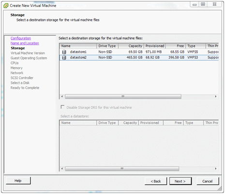
Now we need to decide where disk storage will be allocated to hold the configuration and operating files for the virtual machine. (This is not necessarily the same location as the file system for pfSense software, as shown later.) There are two datastores on this server – a small 80GB drive on which ESXi is installed and a 500GB disc which is for virtual machine storage. Highlight a datastore from the list and click Next.
Virtual Machine Version
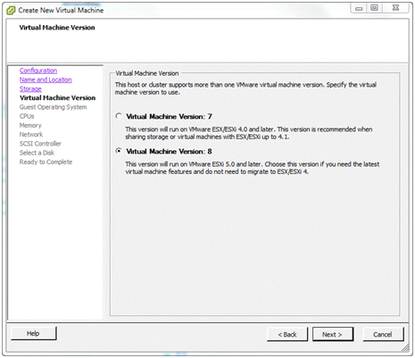
Here is where the virtual machine version to use for the pfSense installation is configured in ESXi. Note the warning above. Select version 8 and click Next.
Guest operating System
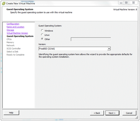
pfSense software is built on the FreeBSD operating system, not Linux. Select Other and chose FreeBSD (32-bit) or FreeBSD (64-bit).
Make sure the hardware is capable of running 64-bit virtual machines, which it must be to run ESXi, and download the pfSense ISO image for installation, choosing the amd64 architecture.
Click Next.
CPUs
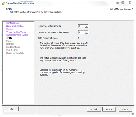
To get started, a single-socket, single-core configuration will do for now. This and other virtual machine settings can always be changed later if needed. Click Next
Memory
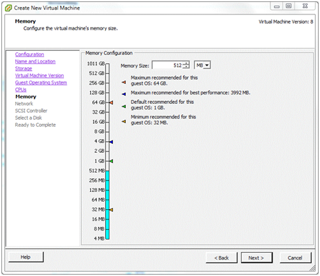
Depending on the number and type of packages that will be installed on the pfSense software, a basic pfSense VM should run comfortably in 512MB of RAM. A lot of simple, non-virtual installations run on old PCs with 256MB and less, so long as swap space is available on the disk. Given the low cost of RAM these days, allocating less than 512MB would not be advised.
If physical RAM on the ESX host is limited - perhaps because lots of other virtual machines will be running - the allocation on the pfSense VM could be reduced to, say, 384MB. If lots of memory-hungry packages will be run, give it more.
To change the memory allocation to one of the sizes shown on the scale of the memory “thermometer”, click that value on the scale. Click Next
Network
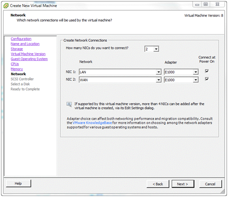
Remember that the two virtual networks were renamed to LAN and WAN. This is where we attach those networks to the pfSense virtual machine.
Select the number of virtual NICs for use by the pfSense VM. In this case it will be 2. Now, using the drop-down lists assign NIC 1 on the virtual machine to the WAN network. Assign NIC 2 to LAN. (This is why the virtual machine port groups were given these names – they are much easier to recognize.)
Note
On pfSense software version 2.2 and later, the choices in the default configuration are em0 for WAN and em1 for LAN, so WAN should be assigned to NIC 1. This may differ from the screenshots shown here. The interface assignment prompt will no longer appear for hosts using em NICs, so be careful not to attach a LAN to em0!
Note that for each NIC an Adapter type may also be selected. Different adapter types may give better or worse performance (and some may not work at all) but that is beyond the scope of this document. To get started, choose the dependable E1000 type for each adapter. Make sure that Connect at Power On is checked and click Next.
SCSI Controller
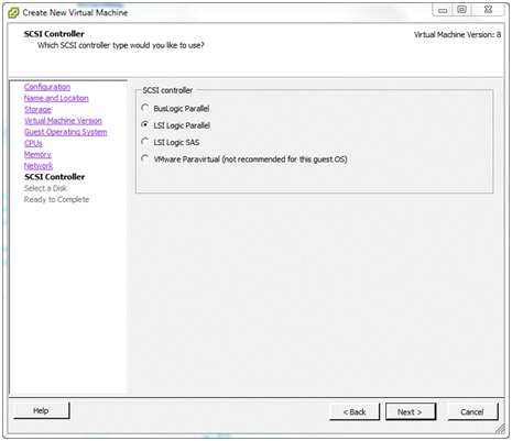
An emulation of an LSI Logic SCSI controller is offered on this system and, as far as I know, the recommendation is based on the operating system of the virtual machine intend to be installed. Accept the default and click Next.
Select a Disk
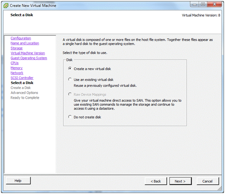
This is where the operating system will build its file system.
Choose Create a new virtual disk and click Next.
Create a Disk
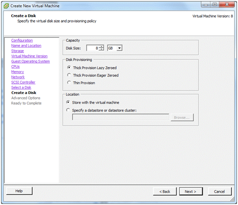
In this example, the virtual disk was given a capacity of 8GB but there is quite a lot to spare and 8GB isn’t really that much these days.
Under Location, keep the virtual machine’s hard disk with the virtual machine itself. Read the help to learn more about this set of options, if desired.
Click Next.
Ready to Complete
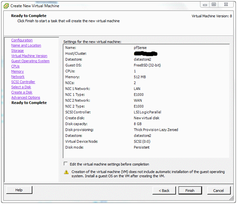
Now a summary of what has been configured so far for this virtual machine is displayed.
Before finishing, check the box Edit virtual machine settings before completion. The label on the Finish button will change to Continue. This will allow the boot CD from which the pfSense software will be installed to be configured. Click Continue.
Editing the Virtual Machine’s Properties
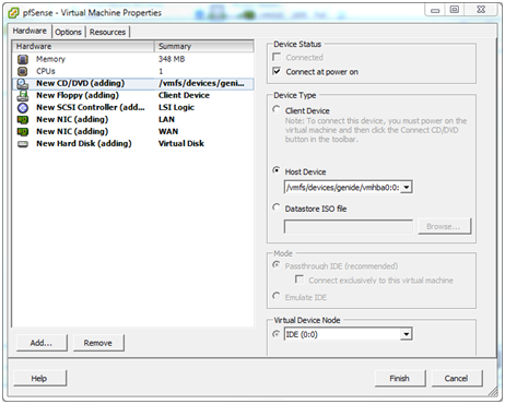
In the Virtual Machine Properties dialog select the Hardware tab and then the line New CD/DVD (Adding) line. In the right-hand pane choose the location of the CD/DVD drive:
Host Device
If a CD/DVD drive is available in the ESXi host, select the CD/DVD drive and check Connect at power on. This change allows pfSense CD/DVD to be inserted into the host’s drive and start installing a soon as the virtual machine is powered on.
Client Device
To install from the CD/DVD drive in the vSphere Client PC, select the Client Device option. As the contents of the CD will be read across the network, this will be a bit slower than using a drive in the ESXi host. In addition, Connect at power on is not available.
Datastore ISO
To install from an ISO image stored in an ESXi datastore, that is also an option but it won’t be covered here. This is much faster than the other options, and more convenient to keep the install media around for re-use.
Click Finish.
Installing pfSense Software
Booting the VM from CD/DVD
Option 1: Installing from the CD/DVD drive on the ESXi host
If the Host Device option was chosen in the Virtual Machine Properties above, slip the pfSense CD into the drive on the ESXi host.
In the left-hand pane of the vSphere client window, right-click the new pfSense virtual machine. A number of actions for VM are displayed, including Power > Power on. Select that or highlight the virtual machine and click the green arrowhead in the toolbar.
Now click the Console tab and the virtual machine will begin booting from the CD.
Skip to Installing pfSense Software.
Option 2: Installing from the CD/DVD drive on the client
If the option was chosen to use the drive in the client PC, put the CD into its drive. Remember that Connect at power on was not a choice if using the client’s CD/DVD drive, so a little bit of extra work is needed to connect it after powering on the virtual machine.
In the left-hand pane of the vSphere client window, right-click the new pfSense virtual machine. A number of actions for VM are displayed, including Power > Power on. Select that or highlight the virtual machine and click the green arrowhead in the toolbar.
Now, with the virtual machine highlighted, click the Console tab.
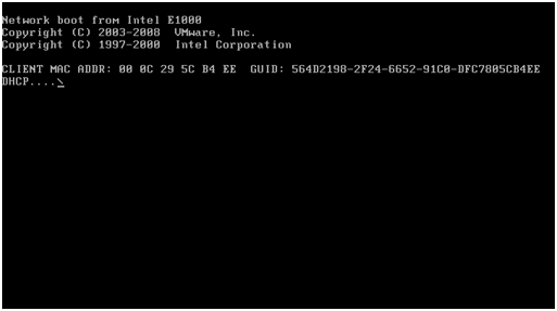
Because the CD drive is not attached to the virtual machine yet, it may attempt to boot from the network or it may be showing an Operating system not found or some other error. Don’t worry about this.
At this point (and only after the virtual machine has been powered on) the virtual machine may be attached to the CD/DVD drive on the client PC. Click on the toolbar icon that looks like a CD with a wrench/spanner. CD/DVD Drive 1 will be offered in the menu and the available choices are displayed. Select Connect to D: (or whatever drive letter represents the CD/DVD drive on the client PC).
Right click the virtual machine in the left pane of the vSphere client and select Guest > Send Ctl+Alt+Del. This will reboot the virtual machine without disconnecting the CD/DVD drive.
In the Console tab, the pfSense installer can now be seen booting from the CD.
Installing pfSense Software
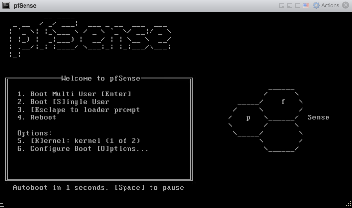
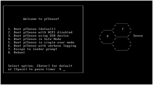
If everything has gone well the pfSense boot menu be shown.
What follows is very much a standard pfSense installation procedure. However, it’s included here to save jumping around between documents.
Note
To enter information through the virtual machine’s console, it is necessary to click inside the console window. To release the cursor, press Ctl+Alt.
Allow the timer to expire and boot the pfSense software from the “Live CD”.
When the following console message is seen:
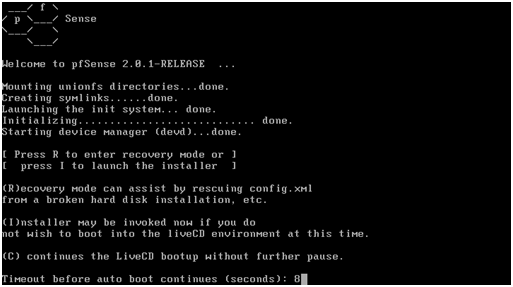
Type i to launch the pfSense installer.
The next few screens are the standard pfSense install screens and are fairly self explanatory. Take the highlighted choice in each of the following screenshots:
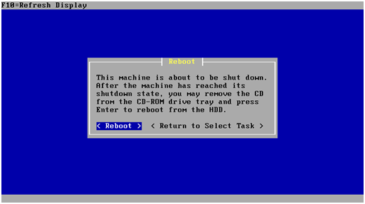
At this point the pfSense virtual machine will reboot and the CD must be removed from the drive.
Interface Assignment
Next up, the pfSense boot menu returns.
As the pfSense software is already installed on the virtual disk, allow the timer to expire.
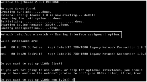
Once the pfSense software has booted the message: Network interface mismatch – Running interface assignment option is shown. This means that the pfSense instance has not yet been told which virtual network interface is LAN and which is WAN.
Note
As mentioned previously, on pfSense software version 2.2 and later, the choices in the default configuration are em0 for WAN and em1 for LAN, so WAN should be assigned to NIC 1. This may differ from the screenshots shown here. The interface assignment prompt will no longer appear for hosts using em NICs, so be careful not to attach a LAN to em0!
First of all, though, as VLANs are not needed, type n and press return.
The order that the virtual NICs were assigned to the pfSense instance when the virtual machine was setup is important here. Generally, ESXi presents those network interfaces to the pfSense instance in sequence. That is, the pfSense virtual machine sees NIC 1 (WAN) as em0, NIC 2 (LAN) as em1, etc.
Note
The MAC addresses assigned to the virtual NICs and seen by the pfSense VM are also virtual. They are not the MAC addresses of the physical NICs.
To double check which virtual NIC is which, right-click the virtual machine in the left-hand pane of the vSphere client and choose Edit Settings. Selecting each of the network adapters (WAN, LAN, etc) will show the virtual MAC address assigned to that interface. Make a note of these to help get the correct virtual interface assigned in the pfSense software. Only the last two characters of the vMAC are generally needed to match them against those shown in the pfSense console. For example:
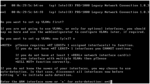
WAN = ee LAN = f8
So go ahead and enter the WAN interface name, em0 in this example, and press return.
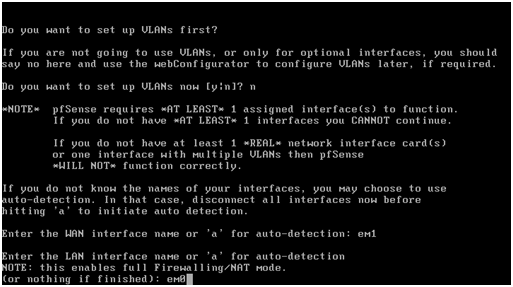
Now enter the LAN interface name, “em1” in this example, and press return.
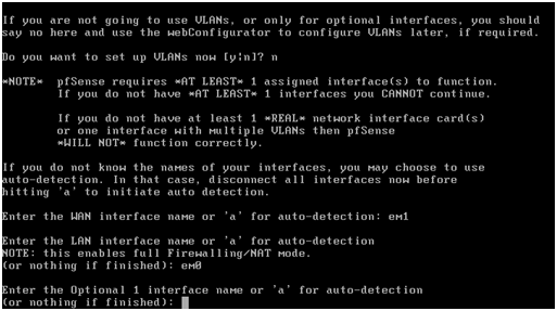
As there are not any OPT interfaces, yet, press return.
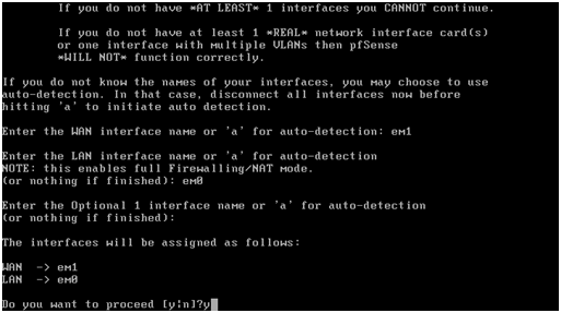
Lastly, check that the interface assignments are correct, enter “y” and press return.
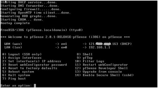
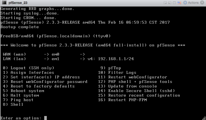
After a short interval, the pfSense VM will reconfigure itself, restart and present the main pfSense screen, above.
If the modem (in this example a simple cable modem) is connected to the physical WAN port of the ESXi host, the WAN interface should have received a public IP address from the ISP via DHCP. ADSL and other modems may need to be set up to pass the public IP through to the pfSense VM. Other types of WAN connections and configurations are beyond the scope of this article.
The LAN interface has its installation default IP address of 192.168.1.1. If another network address and/or subnet is desired, it may be changed from the console or GUI.
Adding a DMZ
Having a WAN and a LAN is fine but perhaps another virtual machine will be added to the virtual network – maybe a mail server or a web server. After all, that is likely to be one of the reasons ESXi was used in the first place – as an alternative to running multiple physical machines.
These kinds of servers should be accessible from the Internet but, at the same time, be protected behind the pfSense firewall. That way access can be controlled to them from both the LAN and the WAN.
Another interesting aspect of virtualization is that it is not necessary to stop at one DMZ. Because the DMZ network can be completely virtual, additional physical NICs are not required. For example, a virtual mail server could be put in one DMZ and a virtual web server in another. Then, by connecting them through the pfSense VM with virtual NICs, all access between the DMZs may be controlled. In addition, if one server is compromised, access to any of the others will be more difficult.
That’s not to say that a DMZ can’t also be connected to a real physical network as well. It may be desirable to connect a game console or video/music server behind the pfSense VM but not have it directly connected to the LAN. To accomplish that, connect a physical NIC to the ESX system and attach it as a DMZ.
Creating the DMZ network
Go to the vSphere client and highlight the ESXi host. Click the Configuration tab and the Networking link. The ESXi network diagram is displayed.
Click the Add Networking link near the top right of the Network pane.

We want to add a new virtual machine network, so select that option and click Next.
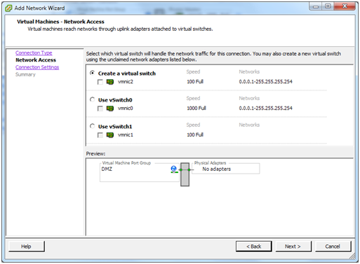
Choose the option to Create a vSphere standard switch. We aren’t going to need a physical NIC – it is going to be virtual - so make sure that if there are more physical NICs in the ESXi host, none of them are selected, then click Next
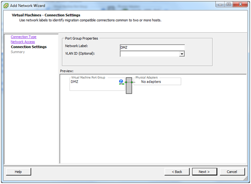
As with the LAN and WAN, give the new network a name. “DMZ” would be good. Click Next.
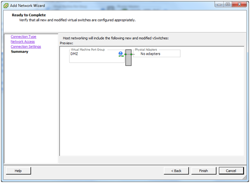
Click Finish.
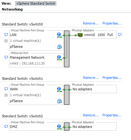
Now the Networking diagram will look like this - just a vSwitch and a Virtual Machine Port group called “DMZ” with no physical NICs attached.
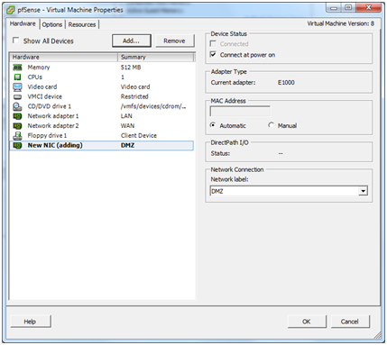
The next step is to connect the pfSense VM to this new DMZ network. Right-click the pfSense virtual machine and select Edit Settings. Click the Add button.
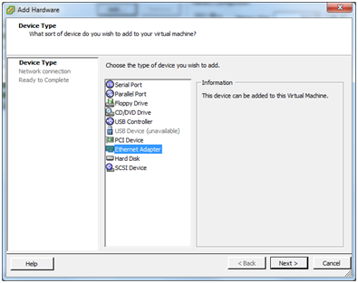
Choose Ethernet adapter and click Next.
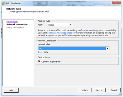
As was done for WAN and LAN, choose the E1000 type of virtual network adapter. Select DMZ from the drop-down list of available networks and choose Connect at power on. Click Next.
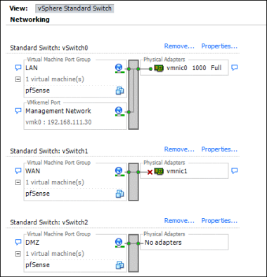
Now the network diagram should look like the above.
Note
all of this may be done while the pfSense virtual machine is still running. To make the pfSense VM aware of the changes, though, it will need to be restarted and then the interface must be assigned.
Now additional virtual machines may be attached to the DMZ network.
Installing VMware Tools
There are a number of benefits to installing the VMware tools, including better memory management, as well as improved network and disk performance. I can’t vouch for those benefits but I find the most useful feature is the ability to shutdown or reboot a virtual machine without needing to log in to it directly. I use this to have all my VMs and the ESXi host gracefully shutdown in the event of a power outage that might exhaust the UPS battery … but that’s another story.
The VMware Tools have been made available as a pfSense package, which makes the install very quick and easy.
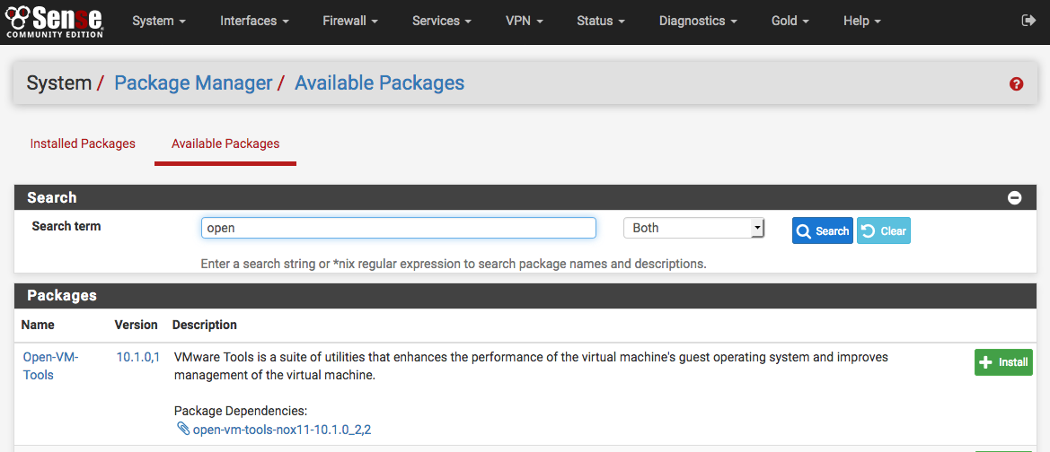
Log in to the pfSense webGUI and click System > Packages.
From the Available Packages tab list, look for the Open-VM-Tools
package and click  on the right to install the package. Confirm the
the package installation and then it will proceed.
on the right to install the package. Confirm the
the package installation and then it will proceed.
There is really nothing to configure with this package, it should just work.
Alternately, the official VMware tools can be used, but it is a much more manual process. See here: VMware Tools