Routing Internet Traffic Through a Site-to-Site IPsec VPN
It is possible to use IPsec on a pfSense® router to send Internet traffic from Site A such that it would appear to be coming from Site B. This may be needed if a vendor requires that connections originate from a specific address at Site B.
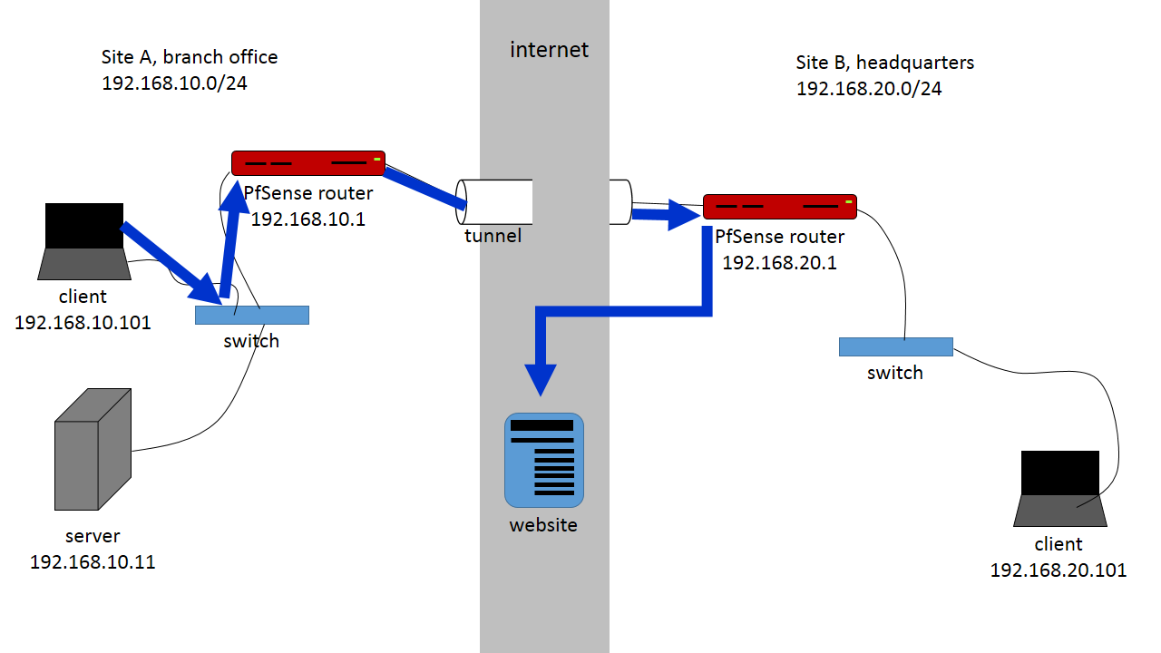
In this article we have two sites:
Site A is a branch office, LAN subnet 192.168.10.0/24
Site B is the main office through which all Internet traffic is routed, 192.168.20.0/24
Set up the IPsec tunnel Phase 1
Site A Configuration
In the VPN menu select IPsec. It opens on the Tunnels tab. Click the + button to create a new Phase 1 setup. (Make sure Enable IPsec is checked and saved.)
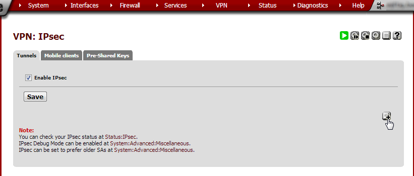
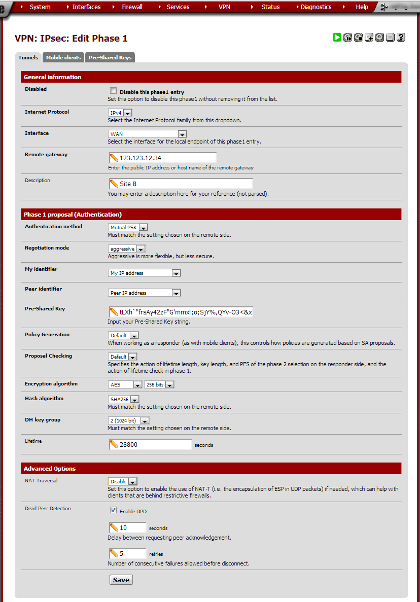
Enter these values:
Field |
Value |
Notes |
|---|---|---|
Internet Protocol |
IPv4 |
|
Interface |
WAN |
Unless using a separate OPT interface |
Description |
Site B |
The site’s locality or another suitable description |
Authentication method |
Mutual PSK |
|
Negotiation mode |
aggressive |
|
My identifier |
My IP address |
|
Peer identifier |
Peer IP address |
|
Pre-Shared Key |
A long key. |
This can be generated using external utilities but be careful to copy it without extra spaces. |
Policy Generation |
Default |
|
Proposal Checking |
Default |
|
Encryption algorithm |
AES 256bits |
Read this comparison of encryption algorithms. |
Hash algorithm |
SHA256 |
Read this comparison of hash algorithms. |
DH key group |
2 (1024 bit) |
Read this explanation of Perfect forward secrecy. |
Lifetime |
28800 |
|
NAT Traversal |
Disable |
Turn this off unless it is definitely needed. |
Dead Peer Detection |
Enable: 10 seconds, 5 retries |
Leave this on unless the other side does not properly support DPD. |
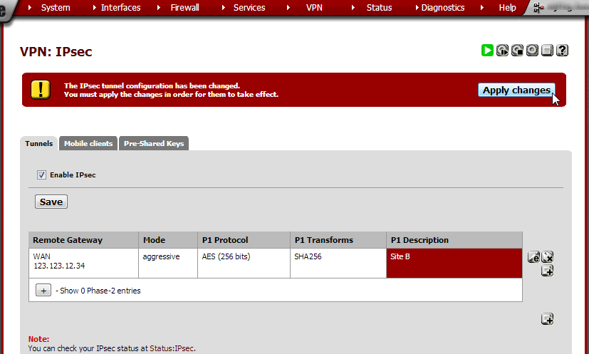
Note that the Phase 1 entry is now shown on the IPsec page. Click Save and in the next screen click Apply Changes.
Site B Configuration
Do the same as in Site A but in the Remote Gateway field enter Site A’s public IP address or FQDN and in the Description field enter ‘Site A’.
Set up the IPsec tunnel Phase 2
Site A Configuration
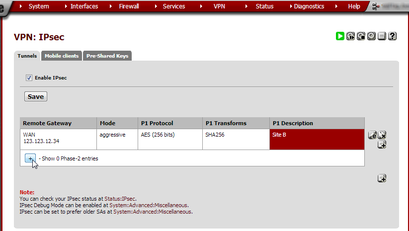
Click  under the Phase 1 entry. It will show an overview of all
available Phase 2 entries. Since we haven’t made any yet none are shown.
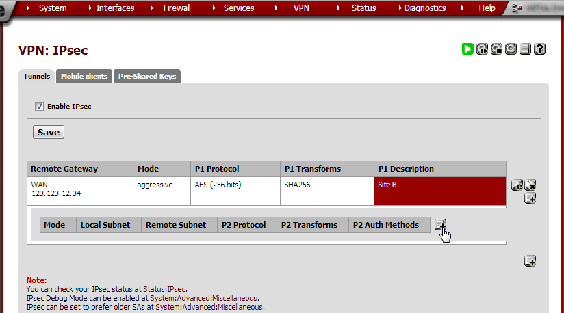
Click  to create a new Phase 2.
Enter these values:
Field |
Value |
Notes |
|---|---|---|
Mode |
Tunnel IPv4 |
|
Local Network |
Type: LAN subnet. NAT/BINAT type: None. |
|
Remote Network |
0.0.0.0/0 |
This tells pfSense to route everything over this interface. |
Description |
Site B |
|
Protocol |
ESP |
|
Encryption algorithm |
AES 256 bits |
|
Hash algorithm |
SHA256 |
|
PFS key group |
2 (1024 bit) |
|
Lifetime |
3600 |
|
Automatically ping host |
Enter a hostname or IP address to keep the tunnel alive. |
In my experience this is not necessary. |
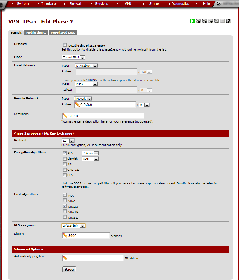
Click Save and on the next page click Apply Changes.
Site B Configuration
Remote Network, Type: Network Local Network, Address: 0.0.0.0/0 Remote Network, Address: Site A’s LAN subnet Use the same Phase 2 proposal and Advanced options as in Site A.
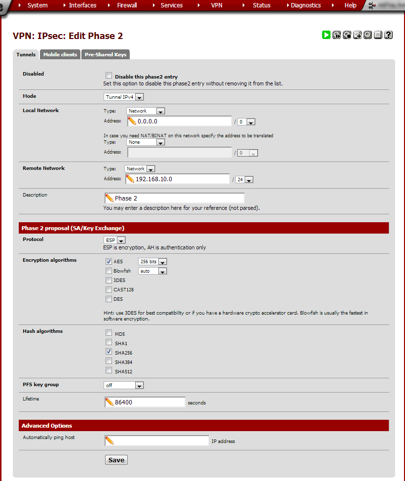
Click Save and then Apply Changes.
Allow IPsec traffic through the firewall
The tunnel should now be operational however no traffic is allowed through it until a firewall rule is added to pass it. The rule must be added to the routers at both sites.
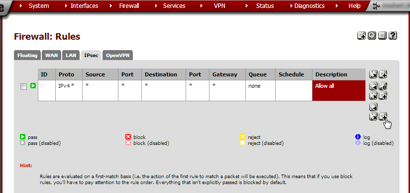
From the Firewall menu, choose Rules. Go to the IPsec tab
and click  .
.
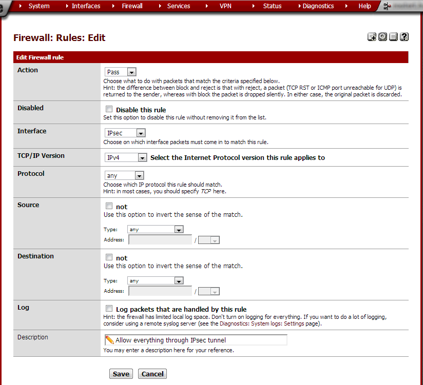
Set the Protocol to any and in the Description field type Allow
everything through IPsec tunnel. Click Save and on the next page
click Apply changes. Do this on both routers.
At this point the tunnel should be up and it should be possible to ping from one side to the other and back. Computers in Site A haven’t got an Internet connection however. This is because we still need to configure NAT for the IPsec tunnel.
Configure outbound NAT
In the default setup outbound NAT is configured automatically. We need to set it to Manual in order to add Site A’s subnet. This configuration step is not required on the router at site A.
Site B Configuration
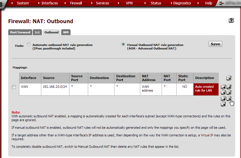
From the Firewall menu, choose NAT and click the Outbound tab. Note that Mode is set to Automatic outbound NAT rule generation. Select Manual Outbound NAT rule generation and click Save. On the next page, click Apply changes.
Click  to open the New Mapping page.
As the Source Type, select Network. In the Source Address field type
Site A’s subnet: 192.168.10.0/24.
In the Description field, type NAT for IPsec tunnel Site A.
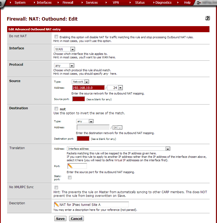
Click Save and on the next page, click Apply changes. The new entry should now be shown in the outbound NAT overview.
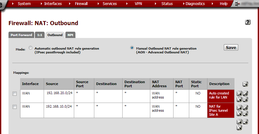
At this point Site B will have a working Internet connection through the IPsec tunnel out Site B’s Internet provider. Any Internet traffic from Site A will look as if it were coming from Site B (see the diagram at the beginning of this article).
By Vorkbaard, 2013-07-27 - gmail{a}vorkbaard[.]nl, with additional edits.